"BIG FOOT 34"
oder
2006_04_14
or
"Modification of the
4-wheel-drive transmission case"
Just
a short report about the places we have been visiting whilst a short trip before
Easter. We preferred to be not too far away from home because our son stayed on
his own at home and in a case of emergency we wanted to be able to be back
quick. Because Anita forgot to take her camera we don’t have any pictures:
Monday,
10.04.2006: Bad Kreuznach – Sarreguemines (Shopping) – Bitche
Tuesday,
11.04.2006: Bitche - La Petite Pierre (Site Seeing: houses in the rocks) –
Saverne (site seeing) – Wangenbourg – Nideck – Oberhaslach – Schirmeck
– Le Struthof
Wednesday,
12.04.2006: Le Struthof - Kaysersberg (Site Seeing) – Colmar
(Site Seeing) – Rouffach
Thursday,
13.04.2006: Rouffach (Site Seeing) – Muhlhouse (Car Museum + Site Seeing) –
Pulversheim (Ecomusée)
Freitag, 14.04.2006:
Ecomusée Besichtigung– Selestat (Site
Seeing) – Mackwiller
Saturday:
Mackwiller (roman temple) – Sarreguemines (Shopping) – Bad Kreuznach
Modification
of the 4-wheel-drive transmission case (4-WD-TC) VG500 to a separated 4-wheel
drive from reduction and blocking
Unfortunately
Mercedes has rated all documents with a copyright, so I cannot publish them here.
Who still needs them: I have got copies available, which I can “loan” upon
request. Besides that I hope that the photos and explanations are sufficient.
Thanks a lot to Pirx (Klaus
Petermann) for all his detailed and helpful information, which I am using
here.
“Why
the heck is he doing that?“ some of you may ask. Well, most of the trucks of
this type the 4-WD is activated by a pneumatic switch and simultaneously the
transmission is reduced plus the blocking between front and rear axle. For heavy
terrain this may be OK but for many cases the normal 4-WD is sufficient – but
WITHOUT loosing top speed! On the other side a reduction of transmission can be
helpful for fine manoeuvring. But if on ground with good grip 4-WD and blocking
of the axles is activated as well this can cause a lot of wind-up in the
components, up to severe damages.
The
“normal” gear-scheme of the 4-WD-TC is as follows (Note: the numbers refer
to the pressure-connections in accordance with the numbers specified on the
papers from Mercedes):
Reduction
and blocking plus 4-WD connected, 11 & 13 bridged by tube
Street-use:
11, 12 & 13 depressurized
--------------
Neutral:
--------------
11, 12 & 13 pressured
4-WD:
12 depressurized
11 & 13 pressured
When
adding another pneumatic switch the above scheme can be changed. The pneumatic
switch is identical to the one for the differential locking of the rear axle.
The Reduction and blocking plus 4-WD connected, 11 & 13 bridged by tube
Street-use:
12 & 13 depressurized
--------------
Neutral:
--------------
12 & 13 pressured
4-WD:
12 depressurized
13 pressured
Additional
pneumatic switch:
Front
axle engaged: --------------
11 pressured
Front
axle disengaged: 11 depressurized
--------------
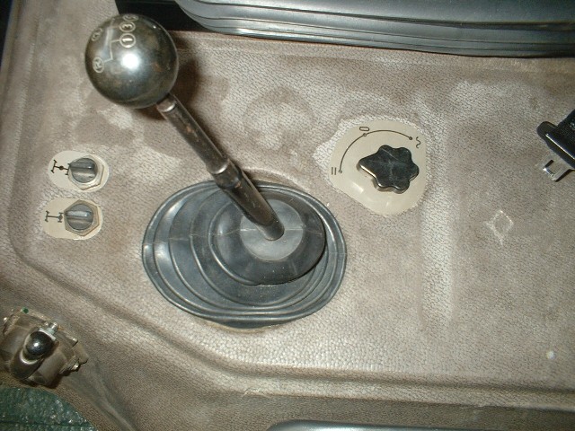
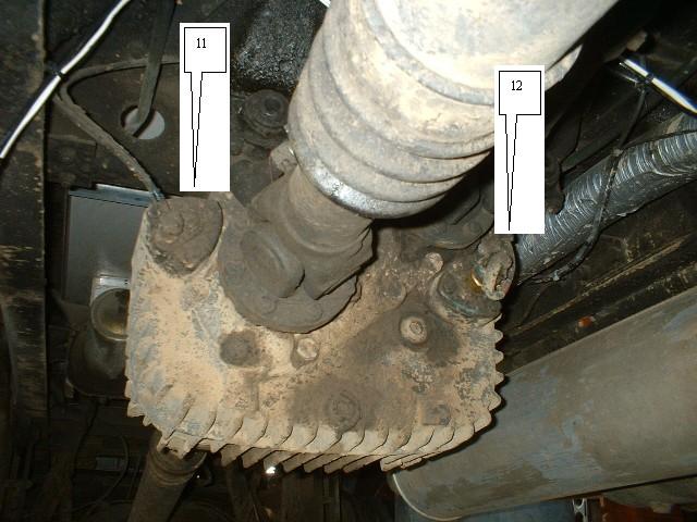
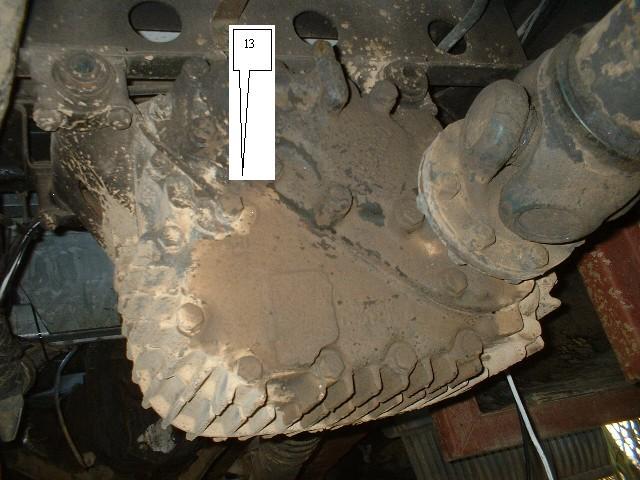
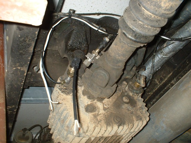
Where
do I find the connections? (Please refer as well to the photos further down!)
Connection
11 is on the front side of the 4-WD-TC, on the right hand side – seen in the
driving direction. (In the original version here is a double air-hose connection
which bridges to connection 13.)
Connection
12 is on the front side of the 4-WD-TC, on the left hand side – seen in the
driving direction. (Here is as well the “original 4-WD-indication light.)
Connection
13 is on the rear side of the 4-WD-TC, on the left hand side – seen in the
driving direction.
All
required parts were till 2006 still available from Mercedes directly! Most of
the items can be organized easily from a well equipped spares dealer, e. g. the
hoses (Tecalan 6 mm, 10 meter is more than enough) and the pneumatic switch 001
997 5036 I got from a dealer for second hand parts much cheaper (original part
2006 approximately EUR 65 incl. VAT) which is identical to the pneumatic switch
of the differential locking of the rear axle. The symbol for the pneumatic
switch can be ordered by Mercedes under part-# 385 584 4324 for approximately
EUR 6,-. Who wants to have an indicator in the dashboard should go for new parts
from my point of view because these items don’t last that long. The
“pneumatic activated light-switch” (e-switch) is connected by putting a
T-hose to connection 11.
Modifications:
In
the base-plate of the drivers-cabin are directly next to the switch of the
differential locking of the rear axle 3 (!!!) more pre-drilled holes for
switches. They can be seen when the drivers-cabin is tilted to the front. The
holes are simply sealed by a plastic cap. So if you cut off the noise protection
foam from underneath you can easily push out the plastic cap and than you only
have to cut out the hole from the floor layer. Afterwards the pneumatic switch
can be fixed easily.
The
supply of pressurised air should only be from a hose, which is behind a safety
valve. Otherwise a possible damage to the pneumatic supply for the transmission
could cause loosing air required for the brake system! I have taken the air from
the “rear-axle differential lock” by putting in a t-connection.
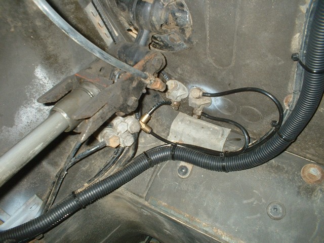
Then
you need to pull a hose from the pneumatic switch to the 4-WD-TC. If you want to
have a light indication in the dashboard as well you should add a double wire
from the dashboard to the 4-WD-TC.
As
already mentioned remove the double air-hose connection from 11 and connect the
pressure-hose to 13.
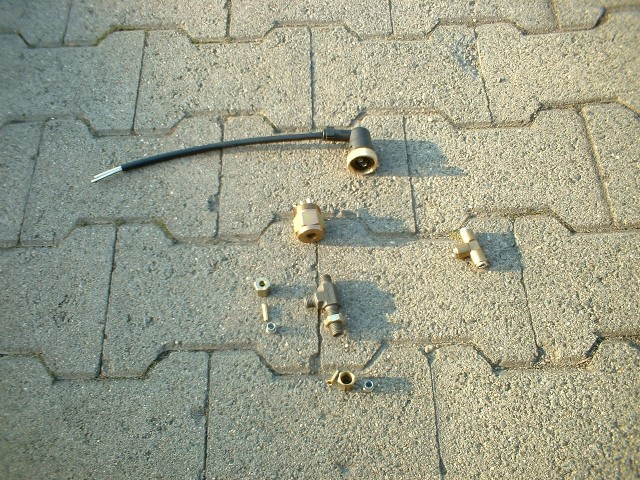
A phot showing
various spares: Electric Connector, Pneumatc Switch, T-Connection plus several
parts for connecting the pressure hoses.
The
new Tecalan-hose connect now to 11. If you want light indication put the T-hose
in between and fix the e-switch to the one side, apply the connector and connect
the cables.
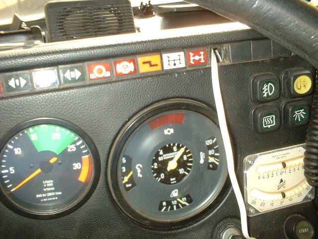
For
the dashboard you need a light-tray (I had a spare one from the formerly
top-mounted yellow warning lights) plus an indicator-cover, which fits
respectively which suits you – that’s it. I am now using the original red
light for "front axle added" (to match the symbol of the pneumatic
switch) and the additional white light for the blocking & reduction.
Mercedes
has a number for this optional version, which includes all parts: SA 25 370.
Only the light-tray and indicator-cover are not included.
Just
in case that someone from you has the 100% fit indicator-cover order-# from
Mercedes – I would appreciate very much your notes!

 Besucher/Visitors
